零知标准板/迷你板低功耗 待机模式lowpower教程实验
本次主要讲解在零知标准板/迷你板上使用低功耗模式的示例,本次演示了standby模式和stop两种模式,待机模式为最低功耗模式理论值为2uA,停机模式为次低功耗模式理论20uA。
一、硬件
1、需要的模块零知标准板或迷你板
2、硬件连接这里主要使用rtc闹钟唤醒,因此无需其他接线,如果使用WKUP引脚唤醒standby 模式,可以接入一个按键到板子PA0(标准板-2,迷你板-11)脚,然后默认拉低,当把其拉高时候就会从standby模式唤醒。
二、软件
(1)standby模式
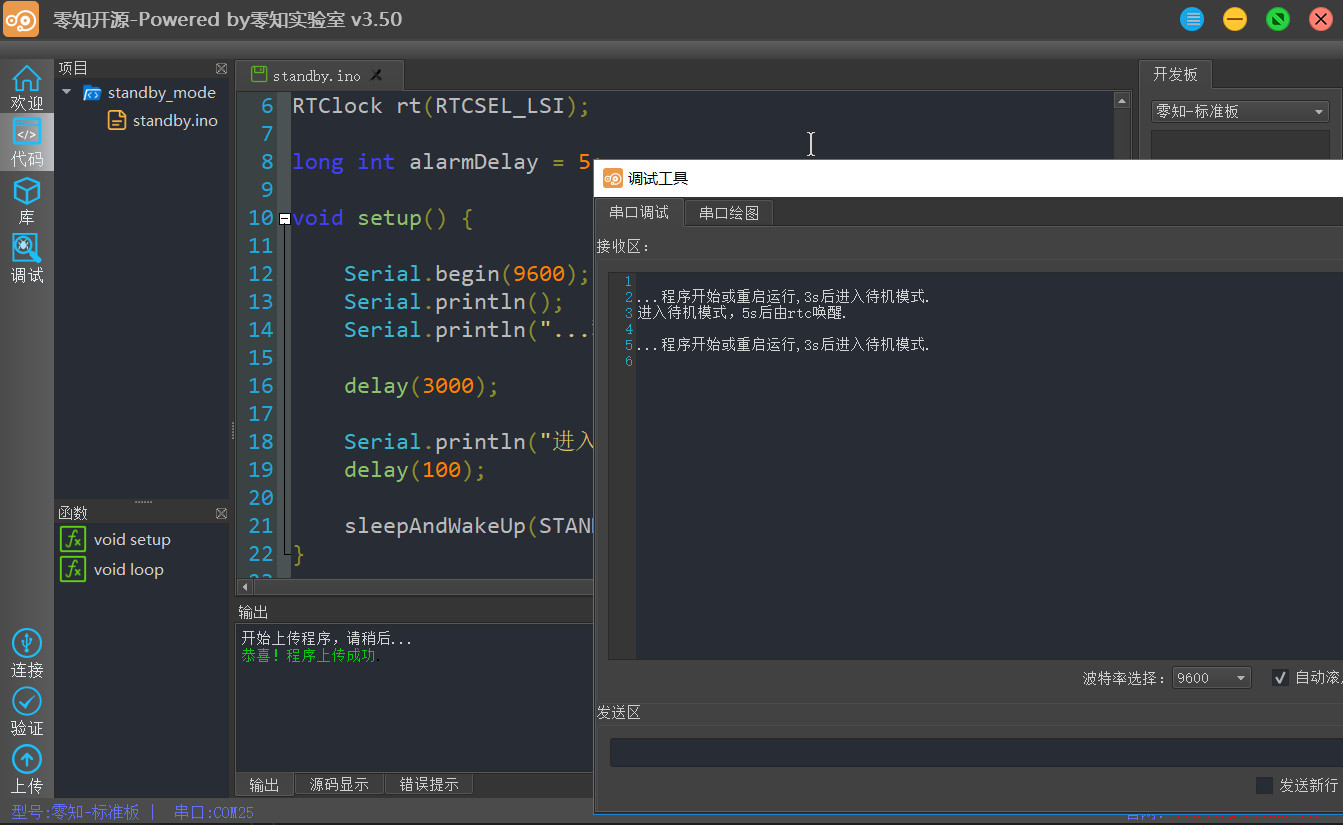
程序功能为程序运行后3s后进入standby,然后RTC 5s闹钟进行唤醒,然后程序就重新开始运行。(也可以wkup引脚唤醒)
#include <STM32Sleep.h>
#include <RTClock.h>
//从RTC唤醒
RTClock rt(RTCSEL_LSI);
long int alarmDelay = 5;
void setup() {
Serial.begin(9600);
Serial.println();
Serial.println("...程序开始或重启运行,3s后进入待机模式.");
delay(3000);
Serial.println("进入待机模式,5s后由rtc唤醒.");
delay(100);
sleepAndWakeUp(STANDBY, &rt, alarmDelay);
}
void loop() {
}
运行结果:
(2)stop模式
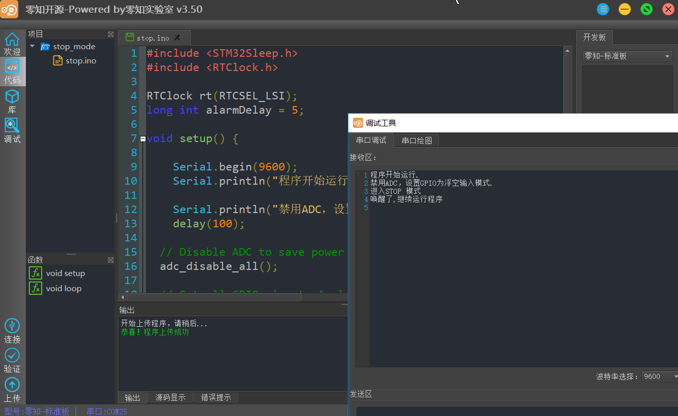
程序功能为:程序开始运行后先禁用ADC外设、设置GPIO脚用于降低功耗,然后进入STOP模式,这里设置RTC闹钟5s后唤醒,5s后唤醒进入正常运行模式继续运行程序。
#include <STM32Sleep.h>
#include <RTClock.h>
RTClock rt(RTCSEL_LSI);
long int alarmDelay = 5;
void setup() {
Serial.begin(9600);
Serial.println("程序开始运行.");
Serial.println("禁用ADC,设置GPIO为浮空输入模式.");
delay(100);
// Disable ADC to save power
adc_disable_all();
// Set all GPIO pins to Analog input to save power (this disables pretty
// much all I/O incl. Serial)
//这里要串口打印,暂时不设置 GPIO
// setGPIOModeToAllPins(GPIO_INPUT_ANALOG);
//STOP mode
Serial.println("进入STOP 模式");
delay(100);
sleepAndWakeUp(STOP, &rt, alarmDelay);
switchToPLLwithHSE();//切换到72M主频
Serial.println("唤醒了,继续运行程序");
}
void loop() {
// We have woken up from sleep! System clock is set to 8MHz HSI.
// Optionally disable peripheral clocks to save power while in Run mode
//disableAllPeripheralClocks();
delay(100); // As the main clock is only 8MHz instead of normal 72MHz this actually takes 900ms
}
运行演示:
附件:软件库-stm32sleep.rar(点击下载)