NRF24L01无线模块使用 2.4G无线通信
NRF24L01是工作在2.4~2.5GHz频段的无线收发芯片,其高速率、低功耗、低成本特点使它在很多场景下得到应用;本次就使用两个NRF24L01在零知平台上进行数据通信演示。
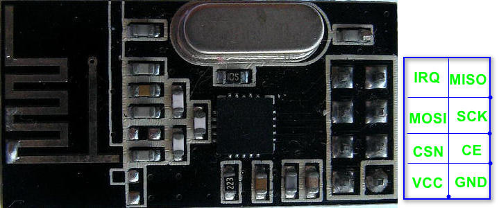
一、模块说明
vcc供电为3.3v,CE为芯片使能脚。
二、连线:
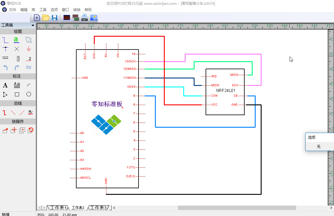
此处的SPI接口连接到默认的SPI1接口上,IRQ引脚未使用。
三、代码
为了程序简单明了,这里分别做接收端和发送端进行测试。
1)接收端程序:
/**
* 文件: NRF24L01-Receiver.ino by 零知实验室([url]www.lingzhilab.com[/url])
* -^^- 零知开源,让电子制作变得更简单! -^^-
* 时间: 2018/10/19 15:11
* 说明:
**/
#include <SPI.h>
#include "nRF24L01_STM32.h"
#include "RF24_STM32.h"
//使用 SPI-1; CE:9, CSN:10
RF24 radio(9,10);
//地址
//byte address[][6] = {"1Node","2Node"};
const uint64_t address[2] = { 0xF0F0F0F0E1LL, 0xF0F0F0F0D2LL };
void setup(){
Serial.begin(9600);
delay(1000);
Serial.println("RF24L01 Receiver");
SPI.begin();
SPI.setDataMode(SPI_MODE0);
SPI.setBitOrder(MSBFIRST);
radio.begin();
// 配置
radio.setRetries(15,15); //失败请求的时间和次数0~15,setRetries(delay,count);延时:delay*250us, 次数:count
radio.setChannel(0x4c);//通道:0~125
radio.setPALevel(RF24_PA_LOW);
//地址
radio.openWritingPipe(address[1]);
radio.openReadingPipe(1,address[0]);
//开始监听
radio.startListening();
//NRF的配置信息,用于调试
radio.printDetails();
}
void loop(){
unsigned long time_buff = 0;//接收到的数据
//接收到信息
if ( radio.available() )
{
radio.read( &time_buff, sizeof(time_buff));
Serial.print("Received: ");
Serial.println(time_buff);
}
}
(2)发送端程序
/**
* 文件: NRF24L01-Receiver.ino by 零知实验室([url]www.lingzhilab.com[/url])
* -^^- 零知开源,让电子制作变得更简单! -^^-
* 时间: 2018/10/19 15:11
* 说明:
**/
#include <SPI.h>
#include "nRF24L01_STM32.h"
#include "RF24_STM32.h"
//使用 SPI-1; CE:9, CSN:10
RF24 radio(9,10);
//地址
//byte address[][6] = {"1Node","2Node"};
const uint64_t address[2] = { 0xF0F0F0F0E1LL, 0xF0F0F0F0D2LL };
void setup(){
Serial.begin(9600);
delay(1000);
Serial.println("RF24L01 Receiver");
SPI.begin();
SPI.setDataMode(SPI_MODE0);
SPI.setBitOrder(MSBFIRST);
radio.begin();
// 配置
radio.setRetries(15,15); //失败请求的时间和次数0~15,setRetries(delay,count);延时:delay*250us, 次数:count
radio.setChannel(0x4c);//通道:0~125
radio.setPALevel(RF24_PA_LOW);
//地址
radio.openWritingPipe(address[0]);
radio.openReadingPipe(1,address[1]);
//开始监听
radio.startListening();
//NRF的配置信息,用于调试
radio.printDetails();
}
void loop(){
//发送信息
Serial.println("sending...");
radio.stopListening();
unsigned long time = micros();
if(!radio.write(&time,sizeof(time)))
{
Serial.println("*** failed");
}
delay(400);
}
通信演示
在这里我们需要两个设备进行通信,可以使用两个零知-标准板,然后分别上传接收端和发送端程序,进行测试;也可以使用一个零知-标准板和一个Arduino UNO进行通信测试。下面是Arduino UNO配合测试的程序:
/*
* Getting Started example sketch for nRF24L01+ radios
* This is a very basic example of how to send data from one node to another
* Updated: Dec 2014 by TMRh20
*/
#include <SPI.h>
#include "RF24.h"
/****************** User Config ***************************/
/*** Set this radio as radio number 0 or 1 ***/
bool radioNumber = 0;
/* Hardware configuration: Set up nRF24L01 radio on SPI bus plus pins 7 & 8 */
RF24 radio(7,8);
/**********************************************************/
const uint64_t addresses[2] = { 0xF0F0F0F0E1LL, 0xF0F0F0F0D2LL };
//byte addresses[][6] = {"1Node","2Node"};
// Used to control whether this node is sending or receiving
bool role = 0;
void setup() {
Serial.begin(115200);
Serial.println(F("RF24/examples/GettingStarted"));
Serial.println(F("*** PRESS 'T' to begin transmitting to the other node"));
radio.begin();
// Set the PA Level low to prevent power supply related issues since this is a
// getting_started sketch, and the likelihood of close proximity of the devices. RF24_PA_MAX is default.
radio.setPALevel(RF24_PA_LOW);
// Open a writing and reading pipe on each radio, with opposite addresses
if(radioNumber){
radio.openWritingPipe(addresses[1]);
radio.openReadingPipe(1,addresses[0]);
}else{
radio.openWritingPipe(addresses[0]);
radio.openReadingPipe(1,addresses[1]);
}
// Start the radio listening for data
radio.startListening();
radio.printDetails();
}
void loop() {
/****************** Ping Out Role ***************************/
if (role == 1) {
radio.stopListening(); // First, stop listening so we can talk.
Serial.println(F("Now sending"));
unsigned long start_time = micros(); // Take the time, and send it. This will block until complete
if (!radio.write( &start_time, sizeof(unsigned long) )){
Serial.println(F("failed"));
}
radio.startListening(); // Now, continue listening
unsigned long started_waiting_at = micros(); // Set up a timeout period, get the current microseconds
boolean timeout = false; // Set up a variable to indicate if a response was received or not
while ( ! radio.available() ){ // While nothing is received
if (micros() - started_waiting_at > 200000 ){ // If waited longer than 200ms, indicate timeout and exit while loop
timeout = true;
break;
}
}
if ( timeout ){ // Describe the results
Serial.println(F("Failed, response timed out."));
}else{
unsigned long got_time; // Grab the response, compare, and send to debugging spew
radio.read( &got_time, sizeof(unsigned long) );
unsigned long end_time = micros();
// Spew it
Serial.print(F("Sent "));
Serial.print(start_time);
Serial.print(F(", Got response "));
Serial.print(got_time);
Serial.print(F(", Round-trip delay "));
Serial.print(end_time-start_time);
Serial.println(F(" microseconds"));
}
// Try again 1s later
delay(1000);
}
/****************** Pong Back Role ***************************/
if ( role == 0 )
{
unsigned long got_time;
if( radio.available()){
// Variable for the received timestamp
while (radio.available()) { // While there is data ready
radio.read( &got_time, sizeof(unsigned long) ); // Get the payload
}
radio.stopListening(); // First, stop listening so we can talk
radio.write( &got_time, sizeof(unsigned long) ); // Send the final one back.
radio.startListening(); // Now, resume listening so we catch the next packets.
Serial.print(F("Sent response "));
Serial.println(got_time);
}
}
/****************** Change Roles via Serial Commands ***************************/
if ( Serial.available() )
{
char c = toupper(Serial.read());
if ( c == 'T' && role == 0 ){
Serial.println(F("*** CHANGING TO TRANSMIT ROLE -- PRESS 'R' TO SWITCH BACK"));
role = 1; // Become the primary transmitter (ping out)
}else
if ( c == 'R' && role == 1 ){
Serial.println(F("*** CHANGING TO RECEIVE ROLE -- PRESS 'T' TO SWITCH BACK"));
role = 0; // Become the primary receiver (pong back)
radio.startListening();
}
}
} // Loop
完整工程代码:
两个零知板测试:发送端- NRF24L01-Sender.7z(点击下载);接收端- NRF24L01-Receiver.7z(点击下载)零知板与Arduino UNO测试:零知板下载上面的发送或接收端任意一个程序,配合Arduino UNO测试代码为: GettingStarted.7z(点击下载)